Categories
- Bargain Corner
- Batteries & Holders->
- Cable/Wire->
- Capacitors->
- Circuit Protection->
- Component Kits->
- Connectors & Leads->
- Crystals & Resonators
- Data Cables
- Electrical
- Enclosures->
- Fans
- Gift Certificates
- Hardware->
- Inductors->
- Maker Modules
- Motors
- Optoelectronics->
- Potentiometers->
- Project Kits->
- Relays & Solenoids
- Resistors->
- Semicon. Hardware->
- Semiconductors->
- Sensors & Transducers->
- STEM Kits
- Storage->
- Switches->
- Tools->
- Transformers & Power Supplies->
- New Products ...
- Featured Products ...
- All Products ...


ProMini Programming
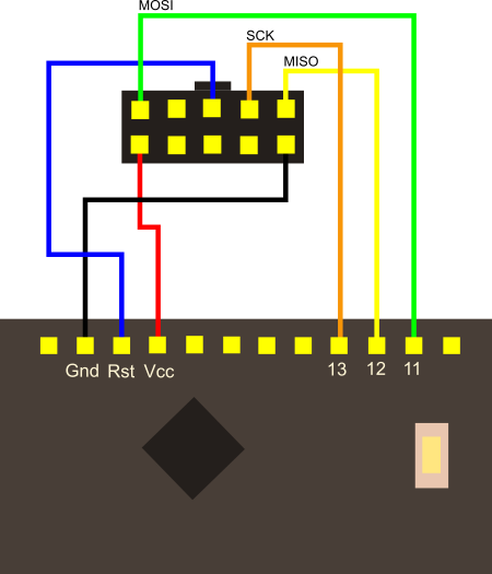
Programming the Pro Mini using the USBasp Programmer
The diagram below shows the connections that need to be made between the programmer 10-pin plug and the Pro Mini. You can make these connections using standard jumper wires or via a breadboard.
Open the Arduino IDE and load your sketch. Select Tools/Board/Arduino Pro or Pro Mini.
Then select Tools/Processor and choose the correct ATMega variant.
Return to the menu and select Tools/Programmer/USBasp.
Select the correct voltage for the Pro Mini on the USBasp and plug it into the USB port - you will probably notice the onboard led begin to flash as the boards are tested by uploading the "Blink" sketch.
Selecting the port from the tools menu should not be necessary, so upload your sketch by selecting Sketch/Upload Using Programmer - do not use the usual toolbar icon. You might get a couple of warning messages at this point, but these can safely be ignored.
Your Pro Mini should be programmed. Error messages are usually the result of poorly or incorrectly made connections, so start there first if you need to do any troubleshooting.